(SMT) and Surface Mount Technology (SMT) has become the predominant method in contemporary electronics assembly. Among its fundamental processes, solder paste printing stands out as a critical operation that directly affects the quality and efficiency of SMT assembly. With the increasing density of electronic components and the miniaturization of parts, the challenges of narrow pitch leads and lead-free processes demand higher standards in solder paste printing. This necessitates a thorough exploration of solder paste printing technology and the optimization of relevant process parameters to ensure product quality.
Solder Paste Deposition Techniques in SMT Production
In SMT production, there are primarily two techniques for depositing solder paste onto PCB pads:
- Screen Printing Technology: This traditional method employs screens made from metal stencils or mesh to apply solder paste. Screen printing is commonly used in high-volume production due to its efficiency and cost-effectiveness.
- Stencil Printing Technology: This direct printing method utilizes metal stencils, allowing 100% solder paste transfer. This technique is particularly suited for low-volume production, where precision deposition is crucial to minimize waste.
1. Screen Printing Technology
The screen printing machine comprises a PCB positioning system, a squeegee system, and a mesh screen. The screen itself, a key component, consists of a frame, mesh, and a mask pattern, typically produced using appropriate methods.
Common materials for the frame include wood, aluminum, and stainless steel, with lightweight alloys preferred for ease of handling without compromising strength. Frames can be categorized into fixed frames, where the mesh is bonded onto the frame using adhesives, or self-tensioning frames that allow the mesh to be directly tensioned to the frame using specialized equipment. This approach is ideal for small-batch, varied production.
Typically, an etched mesh or latex template is used, with materials such as stainless steel or polymer resin fibers. A photosensitive emulsion is applied to the mesh, dried to form a film, and then exposed to UV light with a negative film overlay. The exposed areas create permanent coatings, while non-exposed portions are dissolved, forming apertures for solder paste deposition.
The diameter of the mesh threads and aperture sizes determine the paste deposition thickness. Generally, screen printing is suitable for solder joint heights of over 300 μm and paste viscosities of 400-600 Pa.s, utilizing a squeegee hardness of 70-90. Use a rubber or polyimide resin squeegee with a hardness of 70 to 90. The average size of the alloy powder particles in the solder paste should be no larger than 1/5 of the screen mesh size.
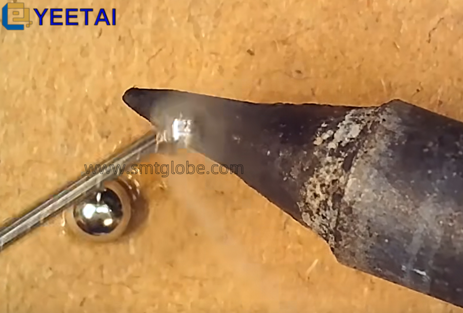
Screen printing is non-contact printing and is prone to solder paste leakage defects (as shown in the figure below). Usually screen printing requirements than the stencil printing operation slower, scraping gap is larger; at the same time for the ease of printing, should use a lower viscosity of the solder paste. In addition, when printing, to adjust the screen and work parallel to the frame and maintain a 0.5mm scraping gap.
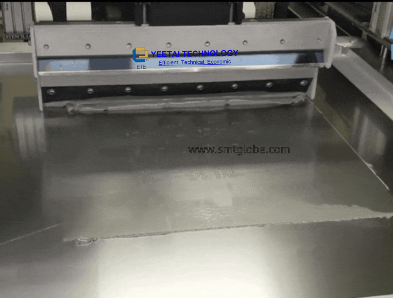
2.2 Stencil printing technology
Stencil leakage printing is a direct printing technology, it is a metal template instead of screen printing machine in the screen. The so-called template is in a piece of metal with a chemical way or with a laser and other methods of engraving out the leakage of the print, unlike the screen openings to prevent the flow of solder paste, so the template can make 100% of the solder paste through the screen can only make about 50% of the solder paste through. Depending on the etching material, stencils can be categorized into selective flexible metal stencils and all-metal stencils.
Fine-pitch solder paste printing is usually done with metal bleed-throughs, so the bleed-through aperture controls the quality of the paste on the pads as well as the bleed-through. The thickness of the stencil determines the thickness of the printed solder paste and the size of the stencil aperture determines the area and shape of the solder paste pattern. Thicker stencils are not good for solder paste release and are prone to bridging due to thick solder paste. Too thin stencils affect soldering quality due to insufficient solder paste.
Generally speaking, the template is only suitable for solder joint height of 100 ~ 300μm within the occasion, suitable for solder paste viscosity of 400 ~ 1200 (general pitch take 600 ~ 800, fine pitch take 800 ~ 1200) Pa.s, the average size of the alloy powder particles should not be greater than the thickness of the template and the width of the 1 / 3. In order to avoid the deformation of the front end of the scraper and wear and tear, it is best to use harder materials, such as metal scraper or hardness of 1 / 3 of the template. In order to avoid deformation and abrasion of the front end of the scraper, it is better to use harder materials, such as metal scraper or rubber or polyimide resin scraper with a hardness of 90.
Stencil aperture ratio refers to the ratio of width to thickness, i.e.: W/T, generally 1.5:1. For CSP and other graphics, the area ratio (AR) must be used, as shown in Figure 3, the value is generally greater than 0.66, the solder paste release rate can reach more than 85%. The perfect solder paste deposition should have the exact same shape as the stencil aperture, i.e. . Where A is the diameter of the solder paste, D is the diameter of the aperture, T is the thickness of the template, H is the thickness of the solder paste. Figure 4 shows the solder paste release rate versus area ratio, in order to improve the solder paste release rate, you can increase the aperture ratio by increasing the aperture width or reducing the thickness, you can also choose the stencil technology with smooth aperture walls.
Stencil printing compared to screen printing, although more complex, high processing costs, but there are many advantages, such as insensitive to the particle size of the solder paste, not easy to block, the solder paste used in a wide range of viscosity, printing uniformity, graphic clarity, more stable, can be stored for long periods of time, etc., and is very durable, life expectancy is about 25 times that of the screen, so it is suitable for high-volume production and assembly of high-density, multi-lead fine-pitch products.
03 Stencil printing process
Stencil printing, for example, the solder paste printing process shown in Figure 5, is divided into two parts: the solder paste is pressed into the printing template aperture and the solder paste is moved to the substrate pads. Printing process parameters set and adjusted for the printing quality plays a very important role, the following parts of the detailed description.
3.1 Pressing the solder paste into the aperture of the printing template
Figure 6 shows the process of pressing the solder paste into the aperture of the printing template, where the rotation of the solder paste plays a big role. When moving the solder paste by means of the squeegee, a friction force acts between the paste and the printing plate surface, which is opposite to the direction of movement of the paste. The solder paste will rotate under the action of this friction, that is, the rolling phenomenon. Once the rolling phenomenon occurs, the solder paste will often collide with the front of the squeegee, changing direction and generating pressure on the front of the squeegee, which is the force that presses the solder paste into the printing template. At the same time, by rolling, there is also a force in the direction of lifting the squeegee. Therefore, in order to realize correct printing, the force of pressing the solder paste into the opening of the printing template and the force of lifting the squeegee must be controlled appropriately.
l Optimal setting of squeegee speed and squeegee angle
Squeegee speed and squeegee angle are the two basic factors for controlling the pressing force (Fig. 7). The optimum setting of squeegee speed is the setting where the solder paste is set so that it does not slide on the printing template, but rolls and moves. The squeegee speed can be varied within the range of 10 to 150 mm/s, generally between 25 and 50 mm/s, 20 to 30 mm/s for QFP with a pitch of less than 0.5 mm, 10 to 20 mm/s for ultra-fine pitch, and generally 12.7 mm/s. It is worth noting that, as the rubber squeegee for printing at a larger pitch or printing at a higher pressure, deformation can form a scratching pit resulting in printing Insufficient volume, so the rubber squeegee printing speed is higher than the metal squeegee, generally close to 2 times.
Know more solutions at our website: www.smtglobe.com
We can help to simplify and qualify your PTH PCB assembly process. We are also helpful at Through-hole process.
AI Spare parts
SMT AGV Robots
SMT cleaning solutions
solder paste process management