In SMT (Surface Mount Technology) production, achieving maximum machine efficiency during automated manufacturing is essential. SMT process software offers a valuable feature that allows users to easily change the positions of SMT feeders. The primary aim of adjusting feeder locations is to minimize the distance between component pick-up and placement positions. This adjustment is also part of the workflow settings.
Let’s walk through the steps for placing SMT feeders effectively:
Step-by-Step Guide
- Arranging Feeders by Order
Click on the “Feeder” tab to arrange all feeder names in the left panel in sequential order, such as A01, A02, etc. - Arranging by Nozzle Number
Click the “Nozzle” tab to organize all feeder names in the left panel based on the corresponding nozzle numbers. - Arranging by Total Material Count
Click the “Total” tab to sort the feeder names in the left panel by the total number of retrieved components, with feeders that have gathered more components listed first. - Arranging Feeders on the Right Panel
Click on the lower “Feeder” tab to have the feeder names on the right panel arranged sequentially, similar to the left panel. - Shortest Distance Arrangement
Click on the “Single” button to list feeder names in the right panel based on the shortest distance for component pick-up. - Dual-Head Pick-Up Arrangement
Click the “Pair” button to arrange feeder names in the right panel for setups that use dual heads for picking components, which is often the optimal choice.
After arranging the feeders, select a feeder name from the left panel (an arrow will appear), then select the feeder name that needs to be replaced. Click the blue left arrow button to display the chosen SMT feeder name in the “NEW FEEDER” position.
Track Switching
When the track switching button is pressed and released, the display will toggle to another track. Pressing it again will switch back to the current track. The 2×8 mm feeder consists of two independent 8mm feeders, and all tracks are controlled via a control panel. However, only one control can be activated at a time; other buttons for advancing, reversing, and winding are effective only for the currently activated track.
Control Buttons
- Forward Button
- Short press: Moves the material tape forward by one step according to the current step setting.
- Long press:
- If no waste tape is rolled: The tape will continue to move forward as long as the forward button is held down.
- If waste tape is present: The tape continues to advance until the button is released.
- Reverse Button
- Short press: Moves the material tape backward by one step according to the current step setting.
- Long press:
- Without waste tape: The tape will continue to move backward without depressing the waste roll.
- With rolled material: The unwinding process can proceed.
- Incorrect waste tape activation: The unwinding process starts immediately.
- Important: When operating the feeder to rewind tape, ensure the pick-up hatch is open or use the lock device; otherwise, the waste tape may break.
- Winding Button
- Pressing the button activates the waste tape motor, which operates continuously until one of the following occurs:
- The button is released.
- It has been pressed for more than 30 seconds while the waste support is not engaged; the tightened waste tape will push the arm down to the cut-off point.
- Pressing the button activates the waste tape motor, which operates continuously until one of the following occurs:
- Settings Button
- Works in conjunction with the forward, reverse, and winding buttons to set step sizes and pick-up positions.
- Status Display
- This displays the current status of all tracks and any error messages. There are generally three types of errors for the 2×8 mm feeder:
- Track Error: Displays if there is a motor error or feeder module sensor error.
- Processing Error: Sent from the pick-and-place machine to the relevant feeder and displayed on the feeder.
- Module Error: If the control unit has an error affecting the entire feeder module, it will be displayed.
- If there are issues with the feeder module, it will show a red indicator, regardless of whether one unit or both LEDs display a red error.
- This displays the current status of all tracks and any error messages. There are generally three types of errors for the 2×8 mm feeder:
It’s important to note that the LED indicating the step size reflects different types of error conditions. A module or track error will blink slowly, and specific instructions are provided in the error guide. If a button is pressed during a module or track error (except for the track selection button), the current step setting will temporarily display, while the status lights remain red. After one second of releasing the button, it will revert to error type display mode.
Conclusion
Understanding the common placement methods for SMT feeders is critical for optimizing production efficiency in electronics manufacturing. By effectively adjusting feeder positions and utilizing the software capabilities, manufacturers can streamline their operations, reduce cycle times, and enhance productivity.
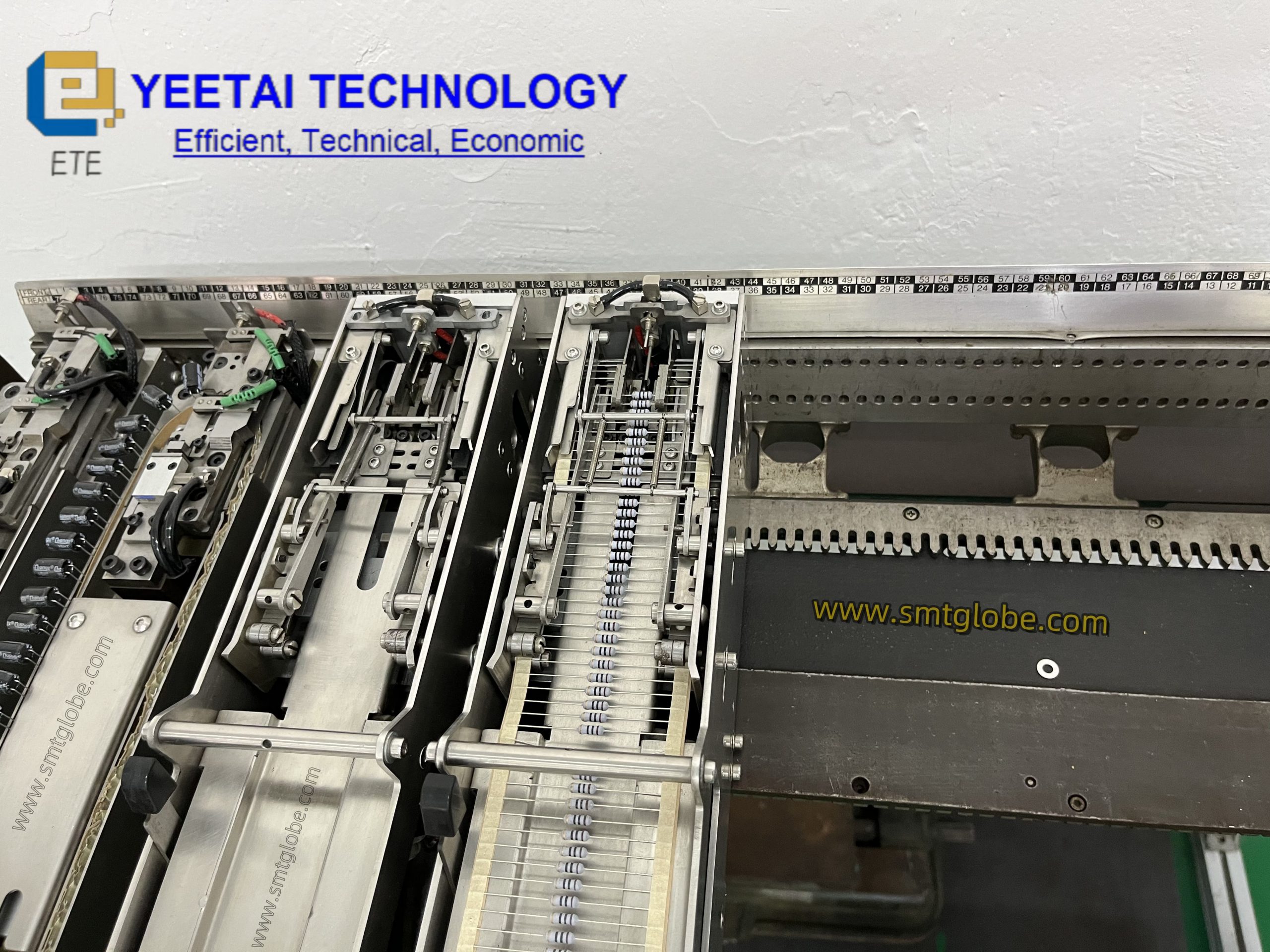
At YEETAI, we produce all kinds of feeder to upgrade SMT machines.