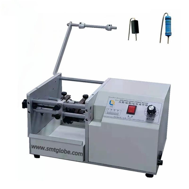
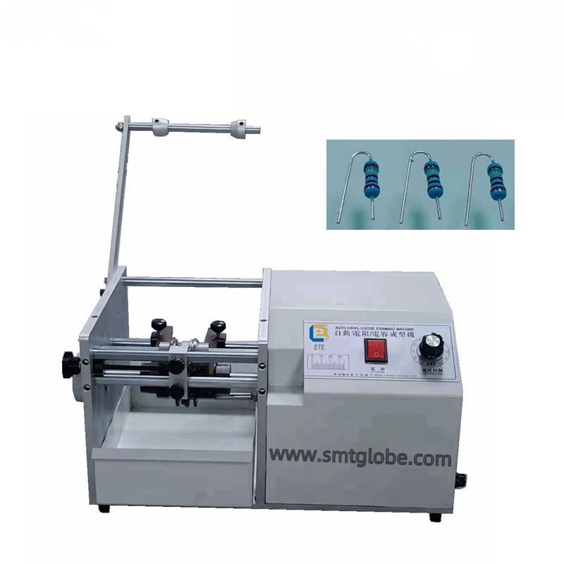
Axial lead cutter and former ETE-201F: Efficient Solutions for Taped Electronic Components
Our Axial Lead Cutter and Former ETE-201F is an advanced cutting and forming machine specifically designed for axial tape-packaged electronic components, including resistors and diodes. Engineered for precision, this machine excels in the efficient cutting and shaping of component pins, making it an essential tool for any electronics manufacturing facility.
Key Features of Axial Lead Cutter and Former ETE-201F
- Compact Design: The ETE-201F boasts a sleek, compact structure that fits easily on any workbench, maximizing your workspace.
- Automation and Efficiency: With motor-driven automation and automatic feeding, the machine enhances production efficiency. The adjustable speed features enable continuous operations for cutting, bending, and feeding.
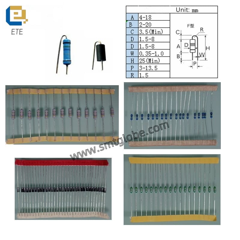
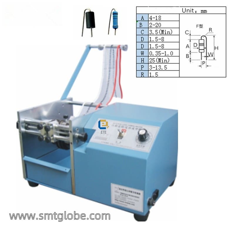
- Customizable Dimensions: Users can easily adjust the pitch and lead length dimensions to meet specific production requirements without the hassle of tooling changes.
- High-Quality Materials: Crafted from premium materials, including Japanese SKD11 tooling and high-temperature powder coating, the ETE-201F ensures superior durability and reliability in electronic component processing.
Technical Specifications
- Power Supply: 220 VAC
- Motor Power: 60 W
- Dimensions: L520 x W380 x H300 mm
- Weight: 23 KG
- Processing Efficiency: Capable of processing between 30,000 to 60,000 pieces per hour
Working Principle
Our Axial Lead Cutter and Former ETE-201F operates by utilizing a stepper motor connected to a drive shaft. When activated, the motor initiates the movement of the drive shaft. Link it to a gear mechanism. This setup allows for the precise movement of the tape feeder, driving the components to the shear position.
At the shear position, redundant pins on the diodes or resistors are cut off using a hob cutter. After cutting, the machine collects residual tape with a dedicated tape roll mechanism. The process continues as the machine moves components to the molding position. Here, two pins bend the ends of the resistors/pins to the desired shape, activating photoelectric sensors to signal completion.
Equipment Overview:
- Sleek appearance, compact structure, can be placed on any workbench
- Axial lead cutter and former is motor-driven, automatic feeding, adjustable speed
- Continuous operations for cutting, bending, and feeding
- Adjustable span and foot length dimensions
Why Choose ETE-201F?
The ETE-201F Axial Lead Cutter and Former stands out due to its unmatched processing capabilities, customizable settings, and robust construction. Ideal for high-volume electronic component production, this machine not only enhances productivity but also ensures optimal precision in every batch.