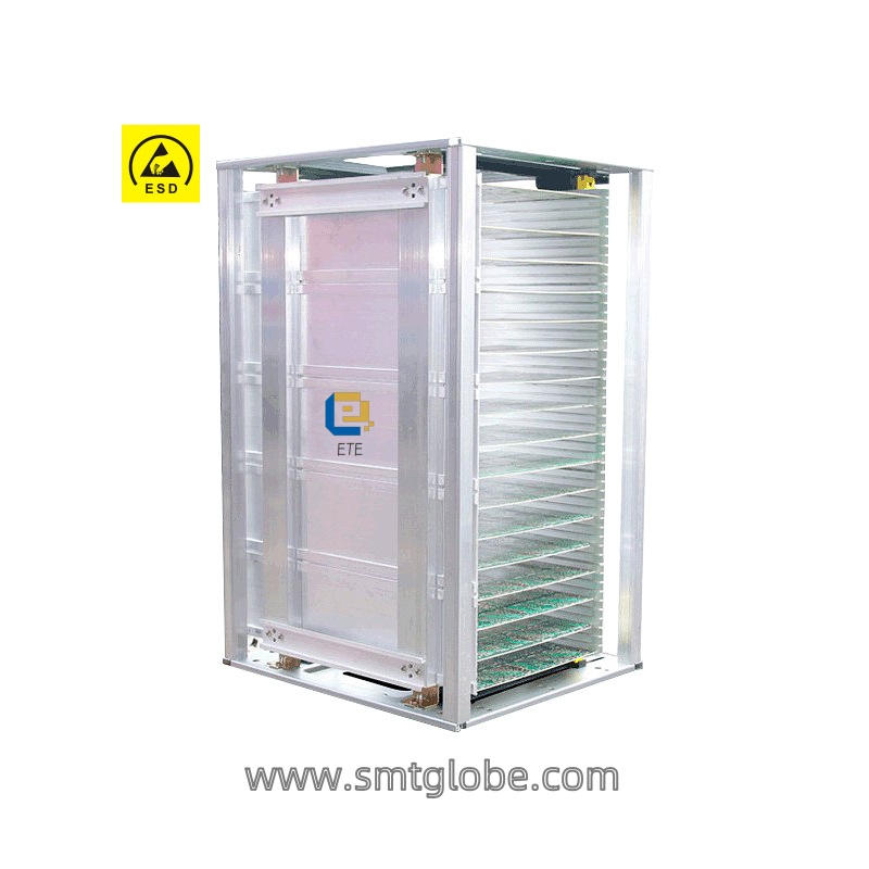
Aluminum Magazine Rack,also known as “SMT magazine rack”. It is designed for seamless PCB storage and retrieval, providing efficient workflow in SMT environments. Smooth moving.
The Aluminum SMT Magazine Rack consists of top and bottom surfaces made of high-quality steel stamped, with premium anti-static plastic injection-molded tooth strips for precise dimensions and smooth adjustment. The fixed plate is secured to the top and bottom surfaces with screws, assembled from 5 aluminum plates and back beams. The plate and back beams are fixed with countersunk rivets, ensuring stability and aesthetics, with smooth edges for easy insertion.
The activity plate of the Aluminum Magazine Rack is fixed in the groove by a pressure buckle, allowing adjustment of the distance between the two plates to accommodate different sizes of PCB storage. When adjusting the plate width, the teeth on the top and bottom surfaces act on the activity plate, driving the gears on the activity plate to synchronize and drive four buckles to slide in the groove, keeping the activity plate parallel to the fixed plate and preventing jamming effectively. Once adjusted, tighten the buckles to secure the activity plate.
Additionally, the pillars of the Aluminum Magazine Rack are made using aluminum extrusion molding process, with a wall thickness of 1.5mm and a unique cross-section design, ensuring structural strength while effectively reducing product weight.
The SMT Magazine Rack is from aluminum alloy and can support usage in high-temperature ovens. It has a wide range usage in SMT processing plants, PCB factories, and computer motherboard factories. The rack is resistant to acid, alkali, and oil, non-toxic and odorless, suitable for storing PCB boards. The magazine rack facilitates convenient cleaning, easy circulation of circuit boards, neat stacking, and efficient management.
With its rational design and superior quality, the Aluminum SMT Magazine Rack is suitable for transportation, distribution, storage, and processing in factories, preventing static electricity on PCBs. It can be used in conjunction with various logistics containers and workstations in warehouses, production sites, and other scenarios, helping enterprises complete the circulation, storage, and integrated management of PCB boards. It is an excellent choice for modern production management in manufacturing and outsourcing enterprises.
Specification
Product model: E39AL
External dimensions: 535 * 460 * 573mm
Usage specifications: length 535 * width 50-390mm
Slot size: slot length 535mm, slot width 7.5mm, slot depth 3.4mm, slot spacing 10mm
Reference dimensions: A: 34mm, B: 34mm
Storage quantity: 50 slots
Adjustment method: gear synchronous adjustment, plate buckle fixation (optional □ screw adjustment)
Static electricity index: surface resistance 10^4-10^8 ohms
Temperature resistance of groove plate: □ 300 ℃
Bottom plate material: metal panel, galvanized carbon steel material
Side panel structure: 5 aluminum alloy panels
Framework structure: aluminum alloy columns, brackets
Baffle mechanism: spring lever
Optional accessories: accept non-standard customization
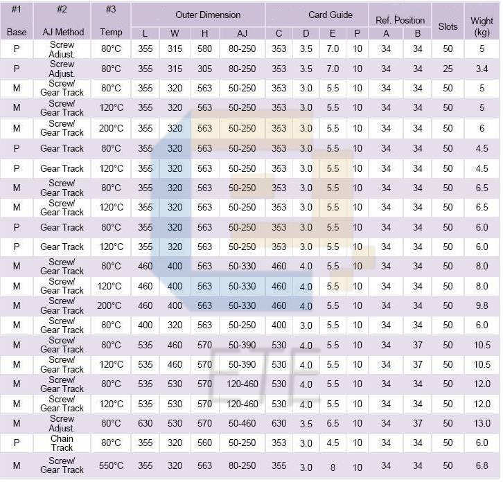
| Product Name | Model | Magazine Size LxWxH | PCB Size(L*W) | PCB Storage Qty | Width Adjustment |
| ESD Magazine Rack | E3353P | 355*320*563mm | 355*(50-355)MM | 50pcs | Screw/Buckle adjustment |
| E4450P | 460*400*563mm | 460*(50-460)MM | 50pcs | Screw/Buckle adjustment | |
| E5550P | 535*460*570mm | 535*(50-390)MM | 50pcs | Buckle adjustment | |
| E5560P | 535*530*570mm | 530*(120-460)MM | 50pcs | Buckle adjustment | |
| Aluminum Magazine Rack | E3325A | 335*320*263mm | 350*(50-250)MM | 50pcs | Screw/Buckle adjustment |
| E4450A | 460*400*563mm | 460*(50-330)MM | 50pcs | Screw/Buckle adjustment | |
| E5450A | 535*460*570mm | 535*(50-390)MM | 50pcs | Screw/Buckle adjustment | |
| E5350A | 535*530*570mm | 535*(50-390)MM | 50pcs | Screw/Buckle adjustment |

How to assemble Aluminum Magazine Rack:
- Press down the gear strip firmly or use a cone to knock it down.
- After installing the gear strip, fix the four corners with screws.
- Take the fixing plate and align it with the holes as shown in the figure, then tighten the screws.
- Flip over the other end and install the movable plate, aligning it with the round hole of the buckle.
- Cover the bottom plate, install the screws, push up the round head of the buckle, and then pull it.
- Place the gear lever on top, assembly is complete.

